| USA
| USA | México
 | India
 | Canada
 | Colombia
 | Brazil
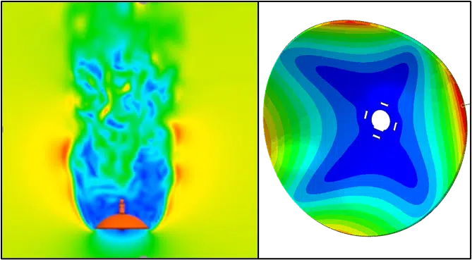
Introduction
Wind loading on dish antenna is an important parameter in designing the antenna structure for communication integrity. The concave shaped reflector surface is the key component for the communications and the deformation caused by wind loading could potentially affect the resolution and sensitivity of the antenna’s performance.
Wind loads and corresponding deformations on the surface can be estimated accurately through one-way coupled Fluid Structure Interaction (FSI). This approach provides a faster and cost-effective approach to estimate the effects of the wind loading on the structures. In the current one-way coupled FSI approach, CFD estimated pressure distribution on the dish surface is mapped to the FE model to estimate the dish surface deformations due to wind loading.
To estimate the wind loading, a commonly used parabolic dish antenna is used to determine the maximum loading on the dish antenna. The wind loads and drag coefficients are estimated for different wind angles to determine the direction of the maximum loading on the dish surface. For maximum loading conditions, pressure distribution on the dish surface is mapped to the Finite Element model to estimate the maximum surface deformation. Figure 1 shows a simplified model of the parabolic dish frame with antenna.
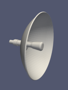
Figure 1: Parabolic Dish Frame with Antenna
SIMULIA XFlow “External Aero” template was used to build the virtual wind tunnel around the dish antenna as shown in Figure 2. XFlow inbuilt wake resolution option was used to capture the wake downstream of the dish antenna.
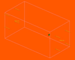
Figure 2: Computational Domain
The analysis was performed at 15-degree orientations starting from 0 degree to 90-degree tilt angles. Figure 3 shows the velocity field around the dish for different wind directions. The velocity in the front of dish structure moves towards a stagnation condition and at the edges of dish structure the velocity values increase to maintain continuity. As a result, the velocity behind the dish is reduced and strong recirculating vortices are generated due to reduced pressure in the dish’s wake.
Figure 4 shows Drag force and Drag coefficient values for different tilt angles. Drag force is high with wind direction along the dish antenna axis and the value reduces with a change in wind direction. Drag coefficient is high for 60-degree orientation indicating the drag force is high for the given projected cross-sectional area.
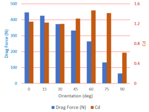
Figure 4: Drag Force and Drag Coefficient for different orientation.
The pressure profile for 0-degree orientation is used to estimate the structural deformations.
A simplified dish antenna model is considered as shown in Figure 5. A fixed boundary condition at the centre of the dish was applied to restrict the movement at the center of the dish in all directions. The mid-point is constrained to the slots and the fixed boundary condition is applied there.
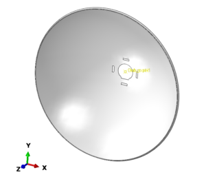
Figure 5: FE Model – Dish Antenna Dome Shell
The Dish surface is spatially discretized using the shell reduced elements, which is reasonable mesh for our study. S4R type of mesh is typically used for the thin shell elements that give relatively low strain values.
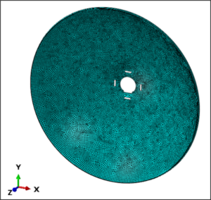
Figure 6: FE Model – Dish Antenna Dome Shell
Pressure data from the CFD model is imported into Abaqus through the process composer. The pressure loading is applied on the front face of the dish as shown in Figure 7.
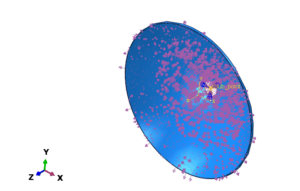
Figure 7: FE Model – Pressure Loading on the Dish
FEA was performed for two different dish thickness. Figure 10 shows the results of the Von Mises stresses on the dish with different shell thickness of 0.8 mm and 0.4 mm. The maximum Von Misses stress for 0.8 mm case is 18.51 N/mm and for the 0.4 mm is 39.29N/mm, which is fairly low compared to the typical yield stress of the steel.
Figure 10 shows the deflection of the dish with deformation scaling factor of 250. There is only 0.09 mm deflection for 0.8 mm thickness and 0.24 mm for 0.4 mm thickness shell.
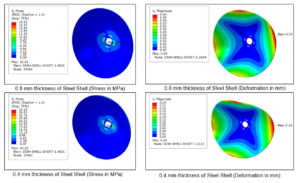
Figure 8: 0.8 mm & 0.4 mm thickness of Steel Shell
This example shows the methodology to estimate the wind loading and corresponding stresses on the dish antenna. A similar fast and cost-effective approach can be used for designing the structures that see high wind loads.
If you want to have a better understanding of wind loading on structures / components, please do not hesitate to contact
- Murthy Lakshmiraju, PhD, mlakshmiraju@viascorp.com or drop a message at https://www.linkedin.com/in/murthylakshmiraju/.
- Arindam Chakraborty, PhD, PE, achakraborty@viascorp.com or connect at https://www.linkedin.com/in/arinc16/
Who we are: Vias3D delivers integrated engineering solutions using simulation-based design and analysis, data analytics, and material testing for a variety of industries including high-tech, energy, process, utilities, transportation, and oil & gas. We bring to our clients dedicated, cost-effective, quick, and safer solutions with an experienced team of simulation experts and industry professionals. Vias3D also provides engineering design, root cause analysis, optimization, project management, operations support, and operations integrity assessment with a combined personnel experience of more than 100 years covering industrial equipment, boiler, and pressure vessel industry, offshore engineering, etc. Vias3D has relevant experience in thermo-mechanical analysis, finite element analysis (FEA) involving large material deformation and non-linearity (geometry, contact, plasticity). Vias3D is actively involved in various codes and standards, ASME (Section II, VII, III, XI), API, and others. Vias3D has workflow automation and GUI customization capabilities. It also provides knowledge transfer through customized training.
Contributors:
Vias3D Engineering Services Team
Murthy Lakshmiraju, PhD, Technical Director at Vias3D
Murthy Lakshmiraju, Ph.D. has over 15 years of advanced use and experience in CFD to solve real life engineering problems for numerous industries, including appliances, energy, oil and gas, marine and chemical processing. He graduated with a Masters and Ph.D. in Mechanical Engineering from Tennessee Tech, USA. He has experience in different flow physics, including advanced turbulence modeling, multiphase flow, heat transfer, Dynamic Fluid Body Interaction (DFBI), Fluid Structure Interaction (FSI), Chimera mesh, Conjugate Heat Transfer (CHT) and reacting flows with combustion and emission modeling.
Arindam Chakraborty, PhD, PE (CA, TX), CTO at Vias3D
He is a mechanical engineer with more than 12 years of strong academic and consulting experience in solid mechanics and design, non-linear FEA, fatigue and fracture mechanics, reliability analysis, composite structures in Oil & Gas, Nuclear, and Structural Design. He holds degrees in Civil (E), Aerospace (MTech), and Mechanical (PhD). He has a strong background in project management, business development, strategy development, and technology development, with a strong focus on public safety regulations (BSEE, NRC). Dr. Chakraborty has strong technical knowledge and working skills in CAE techniques and widely known solutions like Abaqus. He has experience in automating complex engineering problems using codes in FORTRAN/C/C#/VBA/Java/Python GUI scripts. Dr. Chakraborty has more than 25 conference and journal publications, including invited talks at industry conferences and academia. He is closely involved with ASME and API Codes & Standards committees ad task groups.