| USA
| USA | México
 | India
 | Canada
 | Colombia
 | Brazil
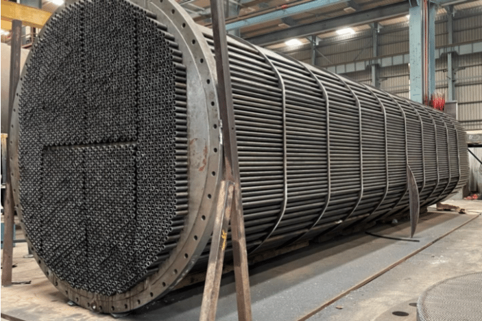
Heat exchangers are among the most widely used components in engineering systems due to the frequent need to maintain specific temperature conditions for process efficiency and safety.
Transferring energy between two fluids through a heat exchanger is often more economical than direct heating via combustion or electrical sources. Moreover, when a process includes both a stream that requires heating and another that requires cooling, coupling them within a heat exchanger improves overall energy efficiency and reduces operating costs of both utilities.
The primary metric of heat exchanger design is to maximize convective heat transfer by increasing fluid turbulence and total heat exchange area. Computational simulation tools are invaluable in this process, as they provide early estimates of outlet temperature, pressure distribution, and efficiency. These outputs allow engineers to evaluate performance, calculate pump requirements, and determine whether a proposed design should advance physical testing and production.
3DExperience FMK is a Computational Fluid Dynamics (CFD) application, developed by Dassault Systèmes, used to simulate and analyze the behavior of fluids and heat transfer in complex geometries. CFD enables engineers to numerically model fluid motion, temperature gradients, and pressure changes within a system, providing detailed insight into phenomena that are difficult or costly to measure experimentally. The platform’s design tools allow users to evaluate how geometry, flow conditions, and boundary constraints affect system performance. The software supports both steady-state and transient simulations, including turbulence and conjugate heat transfer models, and outputs key performance parameters such as velocity profiles, pressure drops, and thermal efficiency—all of which guide design optimization before physical prototyping.
VIAS3D modelled a shell-and-tube heat exchanger using realistic operating conditions. A cold stream flowed on the shell side and a hot stream flowed through the tubes, both at the same flow rate.
The simulation output requests included gauge pressure at both inlets and outlets (surface average) and outlet temperatures (mass average)
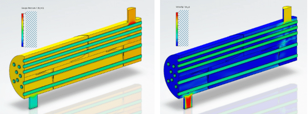
The pressure contour reveals that pressure remains nearly constant throughout the shell, with higher values near the inlet and around the baffles where the flow changes direction. The tube side remains close to atmospheric pressure throughout. The overall pressure drop across the shell is about 43 kPa, meaning a moderately sized pump would be required, making pump selection and operating cost important design considerations.
Flow velocity is highest near the shell inlet and varies along the length of the exchanger, while the tube-side velocity remains steady. Temperature streamlines indicate good mixing of the shell-side fluid around the tubes, especially near the inlet. However, reduced mixing near the outlet suggests that additional or modified baffles could further improve heat transfer performance.
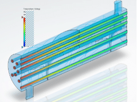
The temperature fields show that the shell-side fluid warms from 338 K (65°C) to 343 K (70°C), while the tube-side fluid cools from 598 K (325°C) to 593 K (320°C) over the length of the exchanger.
The overall heat transfer rate can be calculated using the mass flow rate and the specific heat of Diesel.
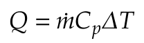
Given a flow rate of 5 kg/s and Diesel’s specific heat capacity of approximately 2.2 kJ/kg·K, the resulting heat transfer is approximately 55 kW. This can be compared to an estimate of heat transfer using the manual calculations of the flow conditions.
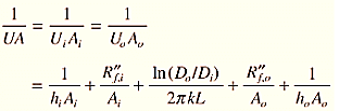
The overall convective heat transfer coefficient method yielded an estimated heat transfer of 60 kW, which closely matches the simulation result. This method also predicts outlet temperatures of approximately 70°C for the cold stream and 320°C for the hot stream, rounding to the same values as the simulation values.
With CFD tools such as 3DExperience FMK, engineers can easily modify geometric parameters or inlet conditions to predict effectiveness, pressure drop, and flow uniformity for various design configurations. This capability makes simulation an indispensable tool not only for heat exchanger design and selection, but also for a wide range of industrial systems involving internal or external fluid flow.
About VIAS3D
VIAS3D engineering and simulation team combines decades of analytical and design experience. They have successfully helped to design various products from many industries for strength, stability, rigidity, and fatigue endurance. Our design and analysis capabilities are accomplished through advanced engineering modelling techniques such as Finite Element Analysis (FEA), Computational Fluid Dynamics (CFD), Electromagnetics (EMAG) and other tools. Using these advanced tools, we can capture complex design features and nonlinearities arising from materials, geometry, and surface interactions to simulate designs and predict their response before they are brought in production.
For more details about our software solutions, training, engineering / PLM services or consulting needs, please email us at achakraborty@vias3D.com, mlakshmiraju@vias3D.com, info@vias3d.com or drop a message on LinkedIn to https://www.linkedin.com/in/arinc16/, https://www.linkedin.com/in/murthylakshmiraju/
Contributors:
Devanik Ghosh, Intern at VIAS3D, is a chemical engineering graduate.
Sai Sandeep Pydisetti, Sr. CFD Engineer at VIAS3D
Mr. Pydisetti has industrial experience in CFD modeling and simulations, consulting, and technical support. He has worked on a wide range of applications, including aerodynamics, acoustics, thermal, multiphase, and reacting flow applications. His professional interests involve CFD simulation and analysis of fluid dynamics and heat transfer applications.
Murthy Lakshmiraju, Engineering Consulting Director
Dr. Lakshmiraju has over 15 years of advanced use and experience in CFD to solve real-life engineering problems for numerous industries, including appliances, energy, oil and gas, and marine, and chemical processing. He graduated with a Master and PhD in Mechanical Engineering from Tennessee Tech, USA. He has experience in different flow physics, including advanced turbulence modeling, multiphase flow, heat transfer, Dynamic Fluid Body Interaction (DFBI), Fluid-Structure Interaction (FSI), Chimera mesh, Conjugate Heat Transfer (CHT), and reacting flows with combustion and emission modeling.